DAY 4
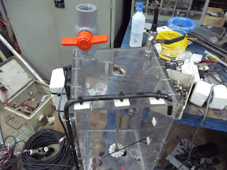
Fig 1: Overall view of digester prototype
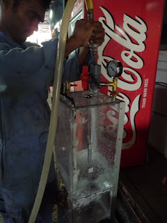
Fig 2: Installed fittings, pressure gauges and pumps
Fig 3: Installed tubings and loading port for the first stage
Fig 4: view of mounted fish tank pumps on the side of the
Fig 5: Top view of the 1st stage
DAY 5
Fig 1: the digester prototype had been shifted to a different workroom. Additional features such as the pressure gauges, ignition valve and gas test socket have yet to be installed. During which, we made several improvisions such as how the gas test socket should be made so that gas cannot escape easily. We had to also go through certain design features and their requirments with the technicians over again to ensure that they followed the design and instructions as well as understand the principles behind it.
Fig 2: the Aerobic stage chamber. We had done some testing with the pumps and the heater to ensure that they were working well. We made certain changes to the prototype, for example a longer tubing to be inserted into the chamber for air to properly bubble through the sludge.
Fig 3: The centre portion of the digester prototype. Still to be installed includes Pressure Gauge and vent.
Fig 4: Additional valves and tubings have been added to the side of the digester prototype. A filter for separating solids from liquids in the sludge has also been added by the other side.
Fig 5: the structure of the Methane Capture System has been constructed. Peforated net to contain the carbon inside has been set up too. Still to be added includes the liquid drainage, the gas test socket and ignition valves as well as the necessary tubing.
DAY 6

Fig 1: Almost finished Digester Prototype. We have decided to scrap the vaccum pump because we were unable to create the vaccum effect using the fish tank pump. Probable causes might be due to the small diameter inlet and outlet. The technicians themselves were also unable to render their help to us regarding this matter. We have decided to let the gas accumulate and compress within the prototype itself and then let the pressure reach equilibrium across the methane system and the prototype system. We have added an additonal ignition valve at the Anaerobic stage chamber to quanitfy the methane gas there too.
Fig 2: We installed the tubing for the liquid drainage in such a way that the liquid can flow through rather easily and will not get congested along the way.
Fig 3: For the u-shaped tubing that allows the gas to bubble through in the methane capture system, we tried several ways to prop a flexible tubing inside the methane capture system. Eventually finding a way (see next fig)
Fig 4: the propped up u-shaped tube inside the methane capture system. The solvent drainage has also been added to the system. However the tube which was supposed to pass through the system to the exterior was wrongly installed, hence, it had to be re-done.
DAY 7
Fig 1: Proceeding to do some final measurements on the prototype to confirm its dimensions. The prototype has been sealed with silicone prior to the water testing.
Fig 2: Preparation for water testing
Fig 3: We closed all valves for water testing and looked for any leakages, gradually opening all the valves to note the ease of flow through all of the tubings.
Fig 4: In addition, we also started the fish tank pump (aeration pump) and heater to test it again.
With this, there was some notable leakages from certain areas, with much delay already on our schedule, we had to quickly reseal the digester with silicone to prevent any further leakages.
DAY 8
Fig 1: The methane capture system had been sealed with silicone and the relevant tubings all attached.
Fig 2: The tube that is to be connected to that of the digester to connect both systems together.
Fig 3: The completed methane capture system with bottom supports.
Fig 4: top view of the completed methane capture system
DAY 9
This day involved the transportation of the completed methane capture system to SVF which was only completed 2 days after the prototype.
Fig 1: the methane system had originally leaked alot and hence was re-sealed again and again. A final re-seal was done at the SVF farm after the system was transported.
Fig 2: The technicians helped with the connection of the methane capture system to the Digester via a tubing that will transport the biogas generated from the sludge to the methane capture system.
Fig 3: The completed prototype
As seen from the figure above, the digester has already been loaded with sludge. The loading will be covered in another post. The prototype was finished a few days behind the scheduled run due to that the construction of the prototype had to be prioritized after the work of the technicians. Despite the delay, we were able to quickly start the 1st run of our experiment and much thanks to the technicians and production manager who heped us, we were able to lead the prototype to compeletion and workable condition.


0 comments:
Post a Comment