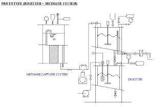
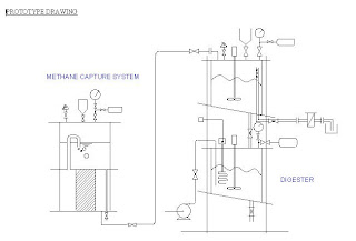
PROTOTYPE DEVELOPMENT
Fig 1: Original Design done by Dr Han
Fig 2: Improvised version of design that better meet our requirements
Fig 3: Introduction of Methane System which has been discussed before.
At this point, the new changes compared to the raw prototype design can be summarized below:
For the ANAEROBIC PROCESS:
Gas test socket has been moved to the first stage. Any Drager Tube can be inserted into the gas test socket. Working principle of gas test socket is to purge first to rid of any contaminant gases inside the socket initially, followed by the insertion of the drager tube through the rubber seal. The valve is then cracked open to allow gases from the digester to enter the gas socket, allowing us to quantify the gas concentration. (see diagram below for better understanding)
Fig 4: Gas Test Socket
Vacuum is applied to the first stage to ensure that no air is present via the vacuum pump
During operation, bypass to methane capture system is open to normalize the pressure inside.
Prevents overpressurization caused by biogas production since it is compressed due to the limitations of vessel size and also to overcome the resistance in carbon bed to methane capture system
Pressure will eventually reach an equilibrium between the methane capture system and the digester
The canister used is transparent, therefore sight glass is not needed.
Liquid drainage from the 1st stage is achieved by inserting a pipe with holes.
Sampling is done for 1st stage after dropping sludge into the 2nd stage to collect from the bottom.
All features added at the side of canister is taken out due to effect on pressure and difficulty to install
Loading port is offset to one side to allow stirrer to be included.
sludge vessel bottom is made slanted to allow easier flow of sludge and installation of stirrer.
Pipe connected 1st and 2nd stage is large to allow the viscous sludge to go down easily.
For the AEROBIC PROCESS:
Aeration is provided using a fish tank pump
Heating circuit is replaced by regular heating coil
Stirrer is mounted below heating coil to avoid collision.
Thermostat control is from the bottom of the vessel
Bottom of the vessel is also made slanted for installation of stirrer
Pressure Gauge and Vent is installed at the top of the vessel.
For OTHERS:
Containment will be in the form of a beaker/ pail
Base of Prototype has to be extended for stability.
For METHANE CAPTURE SYSTEM
- Reverted back to Bicycle Pump System
- System should be easily disassembled for topping up of solvent or changing of solvent
- solvent will be changed to more effective solvents besides waer
- Addition of ignition valve.
- Gas test:
- For 1st gas test: We want to prove the presene of methane by burning gas released through the ignition valve. We can determine the time used to sustain burning and hence, by using gas flow calculation, we can quanitfy the gas produced by the effluent, proving the amount of methane present in the biogas.
- For 2nd gas test: Vessel is to be depressurized. By using the difference in pressure, we can determine the amount of gas that is produced from the digestion.
FURTHER IMPROVISED DESIGNS:
Fig 5: Further improvised diagram of digester prototype + methane capture system
Fig 6: labeled diagram of improvised digester
Fig 7: labeled diagram of methane capture system.
Eventually due to the inability the obtain a rotameter within the limited time span we have and also due to the inability to convert the fish pump into a vacuum pump, we decided to omit these two ideas and carry on with the experiment. Hence, our finalised designs of the prototype are produced. We added an additional ignition valve at the digester to allow us to quanitfy the composition of gases present and totalize it with that of the methane capture system.
FINALIZED DESIGNS
Fig 8: Finalized design of digester prototype + methane capture system
Fig 9: Finalized design of digester prototype (dimensions)
Fig 10: Finalized design of Methane Capture System (dimension)
The sizing of the Methane Capture System is to allow for 60% gas space in the anaerobic chamber and the remaining 40% for liquid and solids. Mass of sludge loaded for each batch is approximately 4.32 kg. Hence the volume of sludge loaded per batch is approximately 5.992 L. Estimated amount of biogas produced is 0.3363 cubic metre.


0 comments:
Post a Comment