To test our results, we planted Kang Kong (Water Spinach) so that we can see the effects each fertilizer has on the plants. This way we can prove that the product, humanure is safe and it works with a certain degree of effectiveness in fertilizing the plant.
0
comments
Friday, October 30, 2009
Fig1. Seedlings of our Kang Kong
Fig2. Seedlings of our Kang Kong in SVF
Fig3. Week 1. Our Kang Kong starting to grow.
Fig4. Week 1. Transferring Kang Kong to open space
Fig5. Week1. Actual digester sample
Fig6. Actual digester sample that got uprooted accidentally by farmer and relocated
0
comments
Sunday, October 25, 2009
PROTOTYPE II- continued.
DAY 4
DAY 4
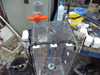
Fig 1: Overall view of digester prototype
Fig 2: Installed fittings, pressure gauges and pumps
Fig 3: Installed tubings and loading port for the first stage
Fig 4: view of mounted fish tank pumps on the side of the
Fig 5: Top view of the 1st stage
DAY 5
Fig 1: the digester prototype had been shifted to a different workroom. Additional features such as the pressure gauges, ignition valve and gas test socket have yet to be installed. During which, we made several improvisions such as how the gas test socket should be made so that gas cannot escape easily. We had to also go through certain design features and their requirments with the technicians over again to ensure that they followed the design and instructions as well as understand the principles behind it.
Fig 2: the Aerobic stage chamber. We had done some testing with the pumps and the heater to ensure that they were working well. We made certain changes to the prototype, for example a longer tubing to be inserted into the chamber for air to properly bubble through the sludge.
Fig 3: The centre portion of the digester prototype. Still to be installed includes Pressure Gauge and vent.
Fig 4: Additional valves and tubings have been added to the side of the digester prototype. A filter for separating solids from liquids in the sludge has also been added by the other side.
Fig 5: the structure of the Methane Capture System has been constructed. Peforated net to contain the carbon inside has been set up too. Still to be added includes the liquid drainage, the gas test socket and ignition valves as well as the necessary tubing.
DAY 6
Fig 1: Almost finished Digester Prototype. We have decided to scrap the vaccum pump because we were unable to create the vaccum effect using the fish tank pump. Probable causes might be due to the small diameter inlet and outlet. The technicians themselves were also unable to render their help to us regarding this matter. We have decided to let the gas accumulate and compress within the prototype itself and then let the pressure reach equilibrium across the methane system and the prototype system. We have added an additonal ignition valve at the Anaerobic stage chamber to quanitfy the methane gas there too.
Fig 2: We installed the tubing for the liquid drainage in such a way that the liquid can flow through rather easily and will not get congested along the way.
Fig 3: For the u-shaped tubing that allows the gas to bubble through in the methane capture system, we tried several ways to prop a flexible tubing inside the methane capture system. Eventually finding a way (see next fig)
Fig 4: the propped up u-shaped tube inside the methane capture system. The solvent drainage has also been added to the system. However the tube which was supposed to pass through the system to the exterior was wrongly installed, hence, it had to be re-done.
DAY 7
Fig 1: Proceeding to do some final measurements on the prototype to confirm its dimensions. The prototype has been sealed with silicone prior to the water testing.
Fig 2: Preparation for water testing
Fig 3: We closed all valves for water testing and looked for any leakages, gradually opening all the valves to note the ease of flow through all of the tubings.
Fig 4: In addition, we also started the fish tank pump (aeration pump) and heater to test it again.
With this, there was some notable leakages from certain areas, with much delay already on our schedule, we had to quickly reseal the digester with silicone to prevent any further leakages.
DAY 8
Fig 1: The methane capture system had been sealed with silicone and the relevant tubings all attached.
Fig 2: The tube that is to be connected to that of the digester to connect both systems together.
Fig 3: The completed methane capture system with bottom supports.
Fig 4: top view of the completed methane capture system
DAY 9
This day involved the transportation of the completed methane capture system to SVF which was only completed 2 days after the prototype.
Fig 1: the methane system had originally leaked alot and hence was re-sealed again and again. A final re-seal was done at the SVF farm after the system was transported.
Fig 2: The technicians helped with the connection of the methane capture system to the Digester via a tubing that will transport the biogas generated from the sludge to the methane capture system.
Fig 3: The completed prototype
As seen from the figure above, the digester has already been loaded with sludge. The loading will be covered in another post. The prototype was finished a few days behind the scheduled run due to that the construction of the prototype had to be prioritized after the work of the technicians. Despite the delay, we were able to quickly start the 1st run of our experiment and much thanks to the technicians and production manager who heped us, we were able to lead the prototype to compeletion and workable condition.
0
comments
Thursday, October 22, 2009
PROTOTYPE DEVELOPMENT II
For this entry, we will focus on the day to day basis of our visits to Tuas (Ensure Engineering) to monitor the progress for the construction of the prototype. We worked hand in hand and very closely with the technician as well as the production manager to ensure that the prototype fits all our requirements. Our frequent discussion ranges from raw materials and instrumentation to be used and suggestions raised by the technicians as well as the production manager.
DAY 1
Fig 1a: Propellers from motors of scrapped machines
Fig 2a: Propellers to be mounted as stirrers
Fig 3a: Technician and Production Manager
Fig 4a: Erection of digester's structure
Fig 5a: Technician cutting parts required for fitting of the digester
DAY 2
Fig 1b: installed stirrers & additional container walls
Fig 2b: Crank of the stirrer
Fig 3b: Transfer valve between two stages
Fig 4b: Structure of methane capture system
Fig 5b: Filter for separating solids and liquids
Fig 6b: Close up of filter (filters excess liquid from the sludge)
Fig 7b: liquid drain pipe inside the digester, held to the wall.
DAY 3
Fig 1c: Fitting of pressure gauges and thermostat
Fig 2c: the modified thermostat and heating coil
Fig 3c: Side view of incomplete digester prototype with thermostat mounted on the wall.
TO BE CONTINUED in the next entry.
0
comments
Throughout the development of the prototype, we had to proceed to make some changes to the original design in order to cater to the problems encountered during the making of the prototype. With our assigned production manager, Mr Euranius, we were able to complete the prototype much to his help and that of his fellow techincians'.
To describe the prototype's development, we must start from the scratch where we obtained a design of the system with the help of Dr Han after a thorough and vigorous discussion with him.
PROTOTYPE DEVELOPMENT
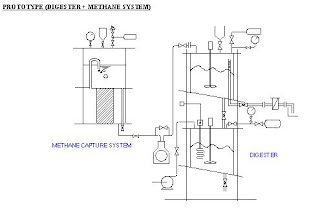
Fig 1: Original Design done by Dr Han
Fig 2: Improvised version of design that better meet our requirements
Fig 3: Introduction of Methane System which has been discussed before.
At this point, the new changes compared to the raw prototype design can be summarized below:
For the ANAEROBIC PROCESS:
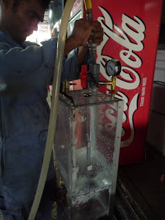
Gas test socket has been moved to the first stage. Any Drager Tube can be inserted into the gas test socket. Working principle of gas test socket is to purge first to rid of any contaminant gases inside the socket initially, followed by the insertion of the drager tube through the rubber seal. The valve is then cracked open to allow gases from the digester to enter the gas socket, allowing us to quantify the gas concentration. (see diagram below for better understanding)
Fig 4: Gas Test Socket
Vacuum is applied to the first stage to ensure that no air is present via the vacuum pump
During operation, bypass to methane capture system is open to normalize the pressure inside.
Prevents overpressurization caused by biogas production since it is compressed due to the limitations of vessel size and also to overcome the resistance in carbon bed to methane capture system
Pressure will eventually reach an equilibrium between the methane capture system and the digester
The canister used is transparent, therefore sight glass is not needed.
Liquid drainage from the 1st stage is achieved by inserting a pipe with holes.
Sampling is done for 1st stage after dropping sludge into the 2nd stage to collect from the bottom.
All features added at the side of canister is taken out due to effect on pressure and difficulty to install
Loading port is offset to one side to allow stirrer to be included.
sludge vessel bottom is made slanted to allow easier flow of sludge and installation of stirrer.
Pipe connected 1st and 2nd stage is large to allow the viscous sludge to go down easily.
For the AEROBIC PROCESS:
Aeration is provided using a fish tank pump
Heating circuit is replaced by regular heating coil
Stirrer is mounted below heating coil to avoid collision.
Thermostat control is from the bottom of the vessel
Bottom of the vessel is also made slanted for installation of stirrer
Pressure Gauge and Vent is installed at the top of the vessel.
For OTHERS:
Containment will be in the form of a beaker/ pail
Base of Prototype has to be extended for stability.
For METHANE CAPTURE SYSTEM
- Reverted back to Bicycle Pump System
- System should be easily disassembled for topping up of solvent or changing of solvent
- solvent will be changed to more effective solvents besides waer
- Addition of ignition valve.
- Gas test:
- For 1st gas test: We want to prove the presene of methane by burning gas released through the ignition valve. We can determine the time used to sustain burning and hence, by using gas flow calculation, we can quanitfy the gas produced by the effluent, proving the amount of methane present in the biogas.
- For 2nd gas test: Vessel is to be depressurized. By using the difference in pressure, we can determine the amount of gas that is produced from the digestion.
FURTHER IMPROVISED DESIGNS:
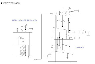
Fig 5: Further improvised diagram of digester prototype + methane capture system
Fig 6: labeled diagram of improvised digester
Fig 7: labeled diagram of methane capture system.
Eventually due to the inability the obtain a rotameter within the limited time span we have and also due to the inability to convert the fish pump into a vacuum pump, we decided to omit these two ideas and carry on with the experiment. Hence, our finalised designs of the prototype are produced. We added an additional ignition valve at the digester to allow us to quanitfy the composition of gases present and totalize it with that of the methane capture system.
FINALIZED DESIGNS
Fig 8: Finalized design of digester prototype + methane capture system
Fig 9: Finalized design of digester prototype (dimensions)
Fig 10: Finalized design of Methane Capture System (dimension)
The sizing of the Methane Capture System is to allow for 60% gas space in the anaerobic chamber and the remaining 40% for liquid and solids. Mass of sludge loaded for each batch is approximately 4.32 kg. Hence the volume of sludge loaded per batch is approximately 5.992 L. Estimated amount of biogas produced is 0.3363 cubic metre.
Subscribe to:
Posts (Atom)